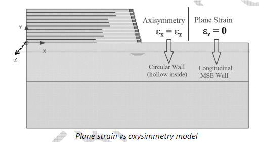
Plane Strain Vs Axisymmetry Model:
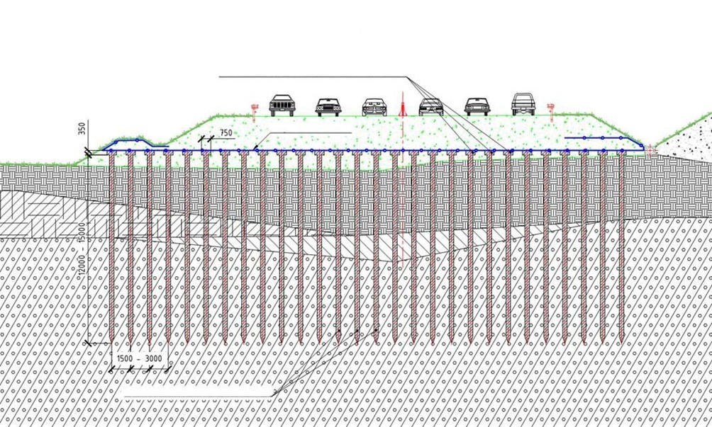
In case of plain strain modelling, the model in the next figure results in a long out of plane MSE wall construction. On the other hand, if axysimmetry model with rotation axis on the left-hand side is adopted, it results in a circular Island shape MSE wall.
The plane strain model means the strains can only take place in the xy plane. Along the longitudinal axis (out of plane direction) the strain is assumed to be zero, εz = 0. Consequently, the length of the MSE wall must be significantly larger than its width.
The axisymmetric model means the lateral, or more precisely, the radial strains of the model are equal in all direction, εx = εz. As the name implies the structures in the model is symmetrical along the vertical y axis and the model is rotated at the y axis, hence the model in the following figure results in a circular island shape MSE wall.
Note: in Plaxis the rotating axis is always at the left boundary.
Failure in choosing the right model of plane strain or axysimmetry will lead to incorrect output
Conclusion: Remember selecting Plane Strain model for our applications
Facing Element Modelling:
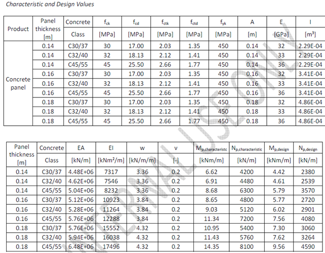
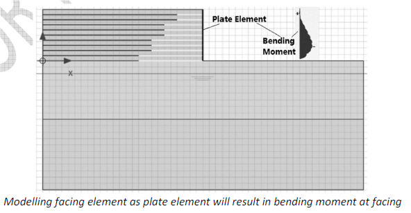
Modelling the facing with plate elements, the analysis will result in bending moment induced in the facing element as shown in the following figure. This type of modelling is developed in case of concrete facing panels and shotcrete facing.
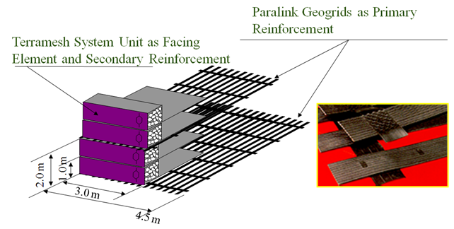
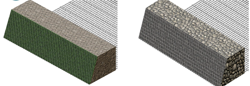
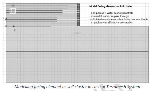
Modelling the facing with soil cluster with the actual dimensions of the facing unit shall be done in the case of Gabion walls or Terramesh System. If water can drain through the facing element, the drainage type is chosen as drained. If water cannot penetrate through the facing element, the drainage type is chosen as non-porous. When the facing units can slip or move one another then ‘interface elements’ should be added in between units.
Conclusion:
For concrete facing elements, plate elements shall be used (MacRes and MacWall).
For all other cases, the facing shall be modelled as Soil cluster.
Initial Stress and Gravity Loading
Often the initial water pressure and the initial effective stresses of the original ground are generated through the so called K0 procedure. The K0 procedure calculates the stresses within the soil body by the following simple equation:

where σh=’ is the horizontal earth pressure at rest, K0 is the coefficient of earth pressure at rest, σv=’ is the effective vertical overburden pressure. This procedure is correct only when all the geometry of the ground surface, the ground layers, and the ground water table are horizontal.
Where the ground surface, the subsoil layer, or the ground water level is not horizontal, the Zm procedure will lead to the existence of unbalanced forces or non-equilibrium of initial forces within the soil body, which are obviously not correct. In such cases, to maintain equilibrium, there should be shear stresses developed within the soil body.
Therefore, the K0 procedure should not be used, instead a gravity loading procedure, where the shear stresses are calculated should be chosen.
The option of gravity loading and K0 procedure in the initial phase is available in Plaxis 2D version 2011 and above. For Plaxis 2D version 9 and below, the gravity loading stage needs to be done by skipping the K0 procedure. This way no initial stresses within the soil body is developed. The initial stresses of the soil body are then calculated in the calculation module of the program by selecting the first phase as plastic ‘Calculation type’, and if any of the soil layer is modelled as undrained, the ‘Ignore undrained behaviour’ option in the ‘Parameter’ tab must be selected (this is since initially, when no external load and no geometry changes is made, the soil is in a drained condition). In the ‘Loading input’ section, the ‘Total multiplier’ option is selected, and in the ‘Multiplier’ tab, key in Σ-Mweight = 1. Then the next actual construction stages are modelled.
Conclusion: Perform Gravity loading procedure for our applications if the geometry is not horizontal

