Mass Gravity Retaining Walls
2020
MUMBAI-PUNE - MAHARASHTRA - India
MSRDC
GABION RETAINING WALL AT MUMBAI PUNE EXPRESSWAY
Problem
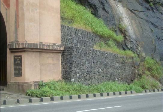
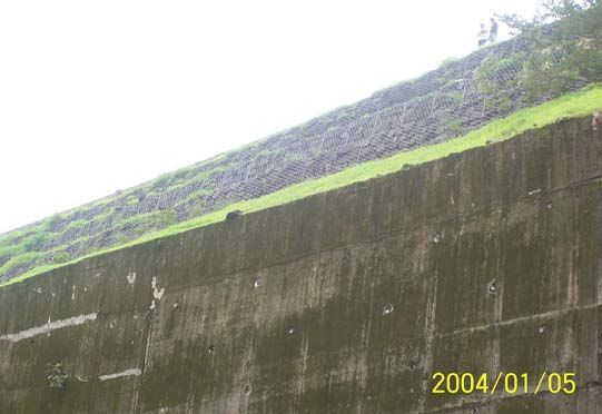
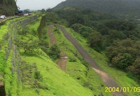
Mumbai Pune Expressway Project involved the construction of a new high speed highway connecting Mumbai to Pune. Gabion walls were mainly used for retention in the Ghat portion of NH-4 between Adoshi to Lonavala. This hilly stretch is about 2 Km in length and is prone to heavy rains during monsoons. Underground waterflows needed large drainage areas. The hill cutting involved the generation of a lot of muck which needed to be disposed (muck is the waste material obtained from tunnelling and hill cutting). On the valley side, the main problem was the global slips. In some of the stretches, rock fall happened where rock ballasting was done
Solution
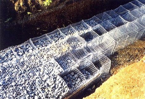
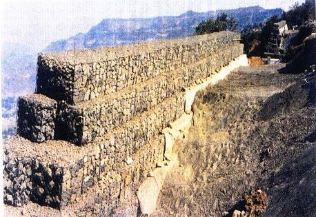
Retaining were deemed necessary. Gabions were preferrred because of its free draining nature and speed of construction. Another advantage of the effective use of stones which were generated from hill cutting were utilised for the filling of gabion walls on the valley side. Wide bases were adopted for Gabion Walls to push slip circles back from the valley edges. Dumped rubbles were used to provide the foundation in the valley side. In some stretches along the hill side, since the rock surface was undulating, it was difficult to excavate the foundation. It was levelled using concrete and some dowels were provided to get proper anchoring to the ground.Maccaferri,10×12,PVC netting was used as rockfall protection measure. The netting was anchored at the top as well as nailed on the surface. The productivity observed was about 2 cum per man day. Lumpsum cost of labour was estimated as INR 100 for lacing, tying and stone filling operations. From aesthetic point of view, stepped rear face walls were adopted at this site as it also proved to have minimum rock cutting. They were placed on PCC leveled rocky strata or 95% compacted environment. To prevent the build up of hydrostatic pressure behind the backfill and to provide free drainage of water through the wall, drainage arrangements were made. This comprised of larger size material at the lower level of the fill and drains for collecting the water. At regular intervals along the walls, transverse drains were made of heavy duty PVC at a slope 1:15 to carry away water from the foundation.
Used Products
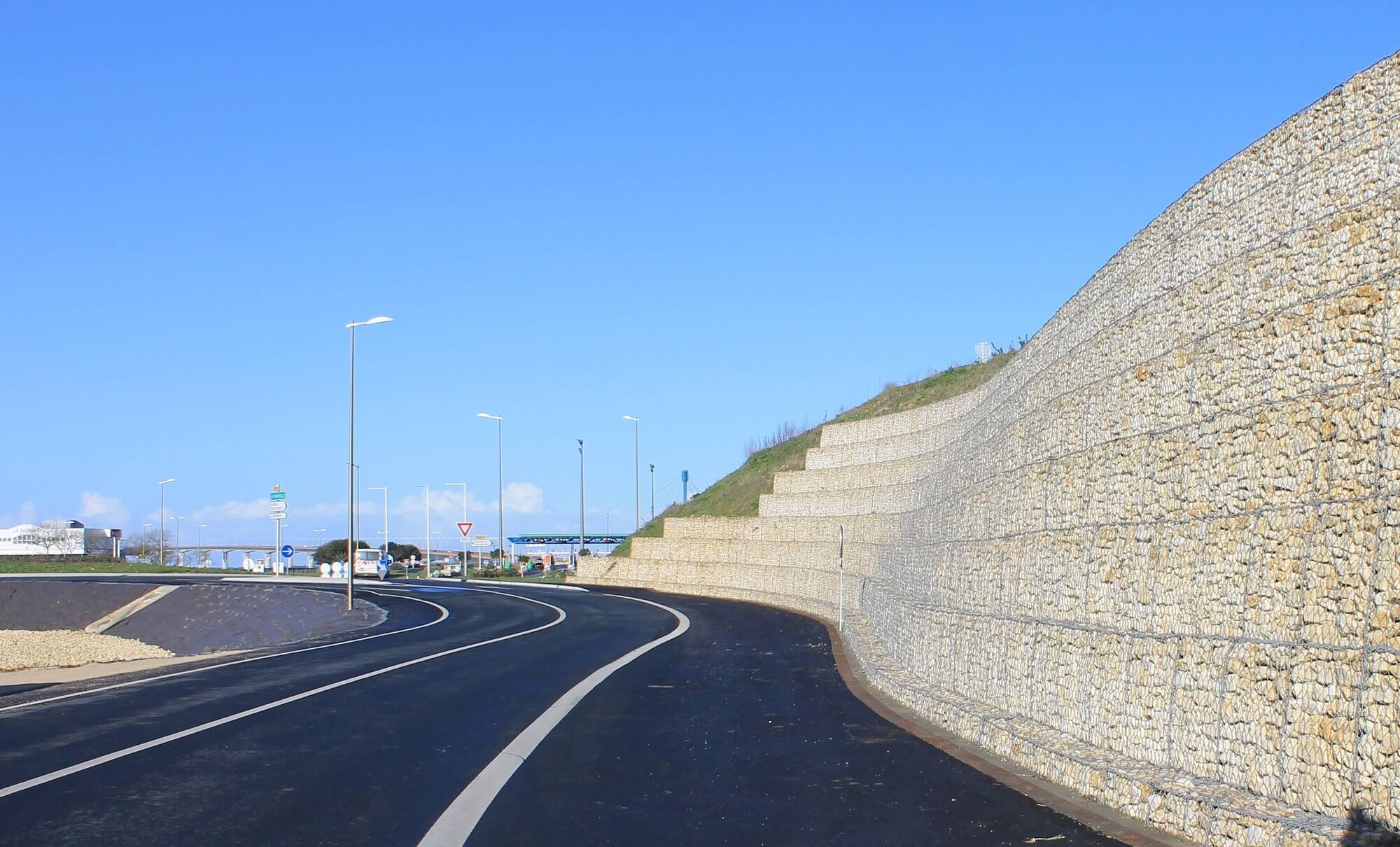
Gabions
Maccaferri Gabion is a Double-Twisted “DT” wire mesh container of variable sizes uniformly partitioned into internal cells, interconnected with othView