Revetment Protection
2023
DUBAI MARINA - DUBAI - U.A.E.
Mirage Leisure & Development
Kier LLC Dubai
Sogreah Gulf
AIN DUBAI OBSERVATION WHEEL PROJECT IN BLUE WATER ISLAND
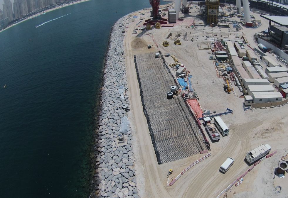
During construction: aerial view of laying of first roll of Paralink 300 geogrid
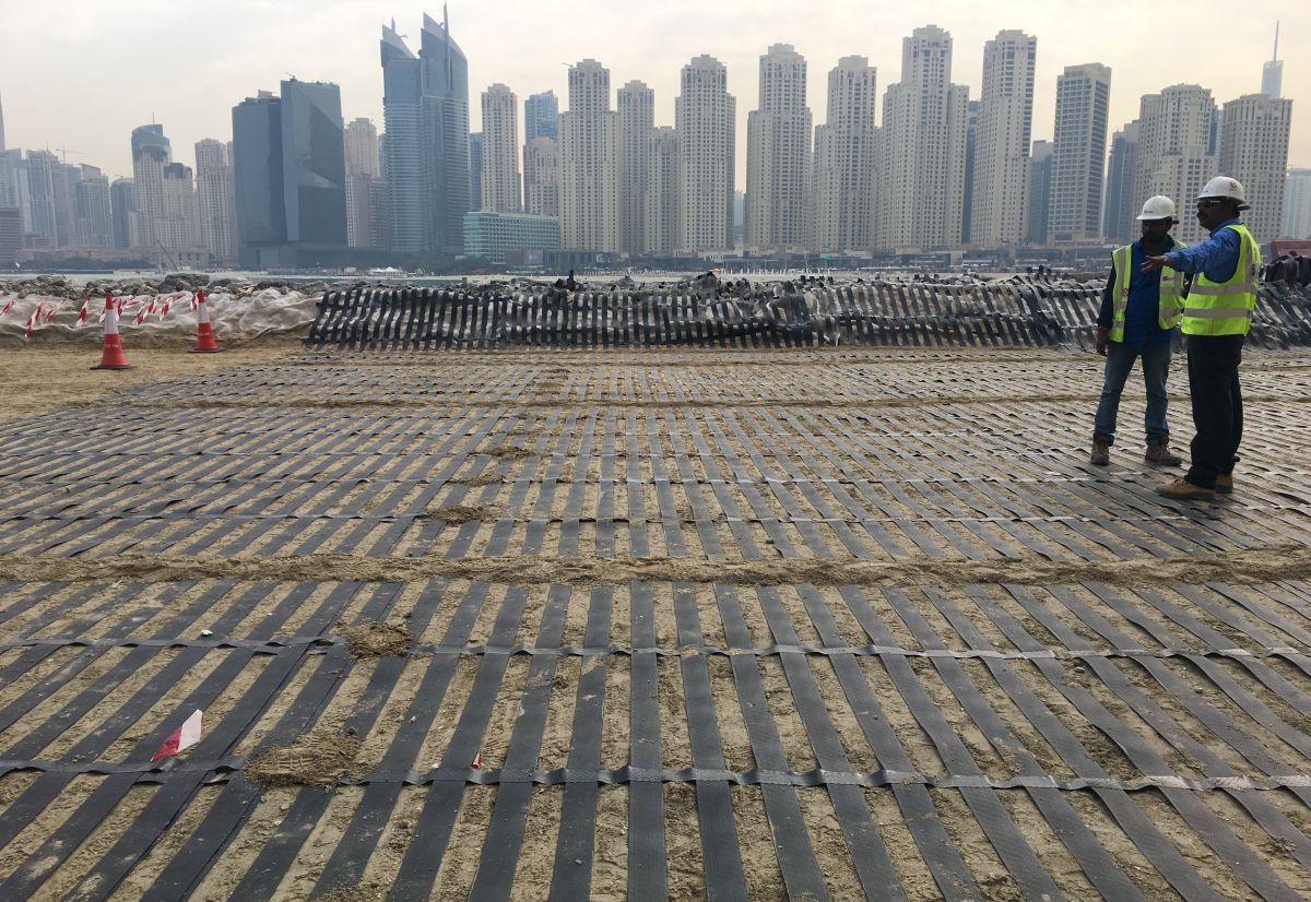
During construction: close view of laid Paralink 300 geogrid layer
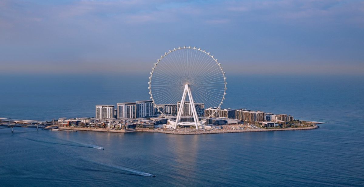
Distant view of completed project (stabilised with Paralink geogrid)
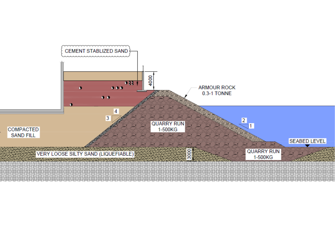
Option-1: Liquefaction mitigation by cement stabilizing the new top fill
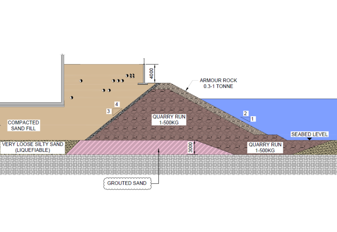
Option-2: Liquefaction mitigation by jet grouting the deep liquefiable layer
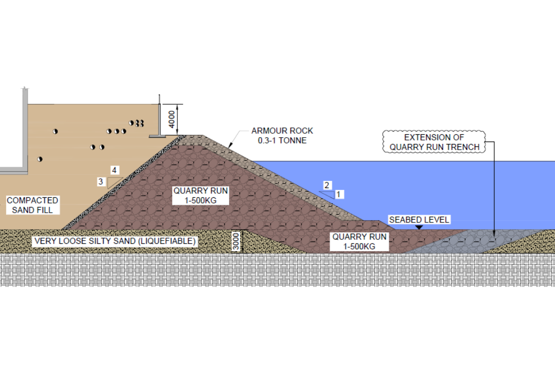
Option-3: Liquefaction mitigation by extension of quarry run at toe of revetment
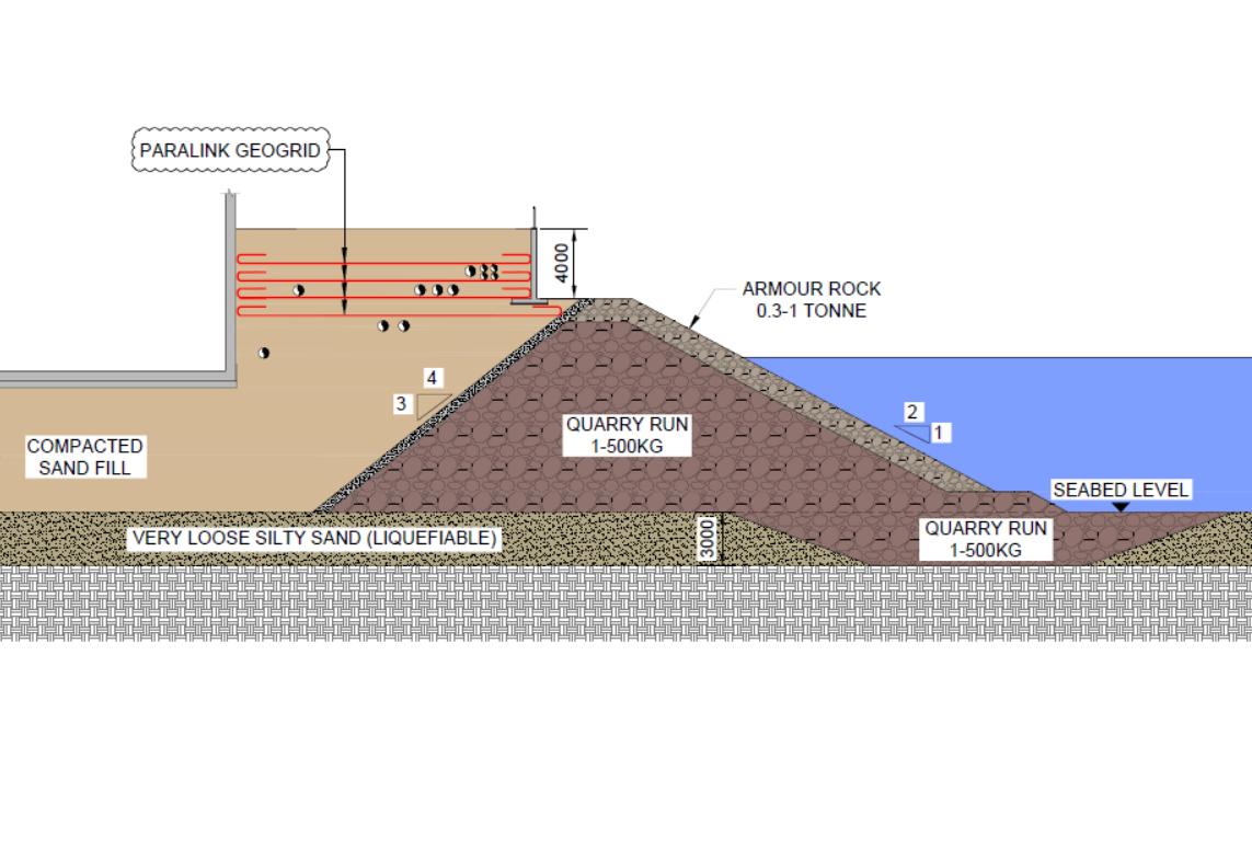
Option-4: Liquefaction mitigation by stabilizing with Paralink 300 geogrid layer
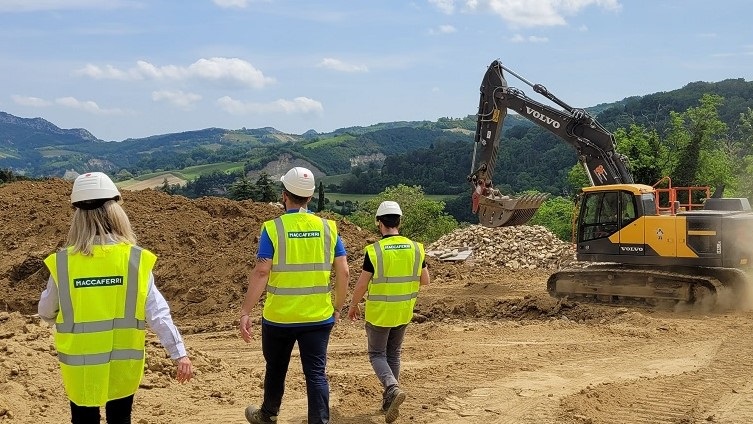
Challenge
‘Ain Dubai in Bluewaters Island’ in the United Arab Emirates is the world’s tallest and largest observation wheel, with a height of 250 m. The project is located close to the Dubai marina and comprises an artificial island with various building structures, including the giant observation wheel. Generally, the ground stratigraphy below the island consists of a 2.5m thick loose marine sand layer followed by calcarenite, sandstone, and conglomerate layers. The average height of the revetment along the island’s periphery is 12m. The initial design of the revetement by the designer identified that the top loose marine sand layer is prone to liquefaction post a seismic event. Therefore, the revetement was dimensioned accordingly. However, due to a revised landscaping scheme at the completion stage of the revetment and backfilling, the client wanted to increase the final platform level by an additional 4m at the top of the original revetment by introducing a concrete retaining wall. For this reason, the factor of safety (FOS) of the original revetment in the liquefaction case proved to fall below the minimum requirement. Therefore suitable mitigation measure was required as per the design basis.
Solution
The most probable failure due to liquefaction post a seismic event was determined as a failure plane along the weak marine loose sand layer resulting in a global FOS less than the requirement. The designer provided several mitigation measures in this regard, including cement stabilizing the proposed new fill at the top (option 1), jet grouting the liquefiable layer below the revetment (option 2), extending the quarry run trench along the revetment’s toe (option 3), or stabilizing the new fill with high strength Paralink geogrids at the top (option 4). The client chose geosynthetic stabilization using Paralink geogrid for its techno-commercial benefits. A key requirement was that the chosen solution must accommodate various utilities at different levels within the new fill. Paralink 300 geogrid layers provided at 1m vertical spacing in the chosen ground stabilization solution could seamlessly integrate this requirement.
Used Products